Napatech Link-Capture™ Software
for Napatech SmartNICs
Feature Overview Data Sheet
PLUG-AND-PLAY INTELLIGENT SMARTNICS
Napatech Link-Capture™ Software provides the Napatech SmartNIC family with a common feature set and driver software architecture allowing plug-and-play support for any SmartNIC combination.
The intelligent feature set offloads processing and analysis of Ethernet data from application software while ensuring optimal use of the standard server’s resources leading to effective application acceleration.
FEATURES
Full Line-Rate Packet Capture
• Zero-loss packet capture for all frame sizes
Full Line-Rate Packet Transmit
• Line rate packet transmit for all frame sizes
Optimized Packet Buffers
• Low CPU load on the host server
Onboard Packet Buffering
• Ensures packet delivery during congestion
HW Time Stamping
• 1 ns time stamp resolution
• Rx time stamp
• Tx time stamp inject with application controlled action per packet
Time Synchronization
• IEEE 1588-2008 PTP V2
• PPS
• OS time
Frame Processing
• Multi-port and multi-SmartNIC data merge
• Frame classification
• Frame and protocol information
• Fixed, dynamic and conditional slicing
• Ethernet FCS verification
Tunneling Support
• GTP, IP-in-IP, GRE, NVGRE and VxLAN tunneling support
• Inner tunnel slicing and filtering of packet headers and payloads
Correlation Key
• Unique identifier for individual packets
Deduplication in Hardware
• Configurable action per port group: discard or pass
IP Fragment Handling
• Identification and distribution of IP fragments
Packet and Flow Filtering
• Configurable filters
• Port and protocol filters
• Pattern compare filters
• IP group match filters with up to 36000 IP addresses
• Up to 36000 flow filters
• Packet discard, forwarding of packet to a specific stream packet coloring and slicing of packet controlled per filter or flow by the application
Flow Identification
• Flow identification based on hash keys
• Multiple protocol-specific hash keys
• Custom hash keys
• Dynamic hash key selection
Intelligent Multi-CPU Distribution
• Configurable flow distribution over 128 Rx streams
• QPI bypass for 2 x 100G performance solution
• 4 x 10G socket load balancer
Host-based Transmission
• 128 Tx Streams
• Transmit on time stamp
In-Line Application Support
• Supports multi-core processing with up to 128 Rx/Tx streams per SmartNIC
• Zero copy transfer from Rx to Tx
• Single bit flip to select packet discard or packet forward
Local retransmit
• Local retransmit with embedded time stamp
Advanced Statistics
• RMON1 port statistics
• Advanced statistics
Monitoring Sensors
• Temperature and power sensors
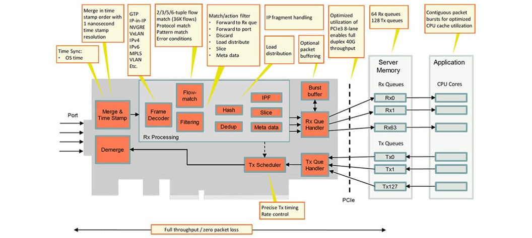
Napatech Link-Capture™ Software decodes all frames regardless of encapsulations and can identify flows based on user-defined header information.
FULL LINE-RATE PACKET CAPTURE
Napatech Link-Capture™ Software optimizes the Napatech SmartNICs to capture network traffic at full line rate, with almost no CPU load on the host server, for all frame sizes. Zero-loss packet capture is critical for applications that need to analyze all the network traffic.
If anything needs to be discarded, it is a matter of choice by the application, not a limitation of the SmartNIC.
OPTIMIZED PACKET BUFFERS
Napatech Link-Capture™ Software uses a buffering strategy that allocates a number of large memory buffers where as many packets as possible are placed back-to-back in each buffer. Using this implementation, only the first access to a packet in the buffer is affected by the access time to external memory. Due to cache pre-fetch, the subsequent packets are already in the level 1 cache before the CPU needs them. As hundreds or even thousands of packets can be placed in a buffer, a very high CPU cache performance can be achieved leading to application acceleration.
The flexible server buffer structure supported by Napatech Link-Capture™ Software can be optimized for different application requirements:
- Applications needing short latency can have frames delivered in small chunks, optionally with a fixed maximum latency.
- Applications without latency requirements can have data delivered in large chunks, providing more effective server CPU processing of the data.
The customer can configure the size of the host buffers from 16 MB to 1 TB.
ONBOARD PACKET BUFFERING
Onboard SmartNIC memory buffers allow packets to be buffered during micro-burst or PCI Express bus congestion situations.
TIME STAMP
High-precision start-of-frame or end-of-frame time stamps, sampled with 1 nanosecond resolution, are applied to all frames received by the SmartNIC. Support is provided for 4 different 64-bit time-stamping formats:
• 2 native UNIX formats with 1 ns or 10 ns resolution
• 2 PCAP formats with 1 ns or 1000 ns resolution
Tx time stamp inject with application controlled action per packet providing:
• Tx time stamp insertion at offset relative to L3/L4 headers
• 8-byte time stamp + 2 bytes for L3/L4 checksum compensation (used in combination with L3/L4 Tx checksums generation)
TIME SYNCHRONIZATION
The SmartNIC time-stamping can be synchronized to that of another SmartNIC or to external sources:
• Synchronization with GPS antennas and other external PPS time sources
• Synchronization with PTP time masters
• SmartNIC-to-SmartNIC HW time synchronization using daisy-chaining of FPGA SmartNICs
• OS time synchronization with dynamic drift adjustment
ONBOARD IEEE 1588-2008 (PTP V2) SUPPORT
Onboard IEEE 1588-2008 support enables connection to a PTP network and synchronization to a PTP master directly from a Napatech SmartNIC.
Napatech FPGA SmartNICs with onboard IEEE 1588-2008 support include Default, Telecom (ITU-1 G.8265.1) profile support. SmartNICs can be used as slave in default, power, enterprise
and telecom (G.8265.1, G.8275.1) profiles. These SmartNICs also provide the possibility of specifying a Packet Delay Variation (PDV) filter to improve time synchronization in a PTP unaware network.
SmartNIC with onboard IEEE 1588-2008 support also provide additional features for enhanced time synchronization. These include the ability to synchronize the host OS time to the time retrieved from PTP as well as the ability to generate a PPS output for synchronization of 3rd party equipment that does not support PTP directly. Napatech provides a complete PTP solution including hardware and software PTP stack.
FRAME PROCESSING
MULTI-PORT AND MULTI-SMARTNIC PACKET MERGE
For FPGA SmartNICs with multiple ports, it is possible to merge packets received on multiple ports into a single data stream for further processing. This is useful for analyzing both receive and transmit directions of a connection, where the packets from the receive and transmit directions are received on separate ports. With Napatech Software Suite it is possible to merge data streams from multiple FPGA SmartNICs into a single data stream for analysis.
FRAME CLASSIFICATION
The Napatech Link-Capture™ Software frame decoder ensures protocol recognition of all major layer 2 to 4 protocols. The frame classification information is provided together with each frame including offset information for encapsulated protocol header and payload data. This provides a significant processing offload and acceleration of analysis.
Frame classification information can be used for:
• Finding protocol headers and payload data at dynamic locations
• Advanced filtering
• Dynamic selection of hash keys (per frame)
• Dynamic slicing
• Intelligent Multi-CPU Distribution
FRAME AND PROTOCOL INFORMATION
For each Ethernet frame received, frame and protocol information is made available to the host application. This accelerates processing of each frame. Information available includes:
• High-precision time stamp information
• Protocol information: e.g. IPv4, IPv6, UDP, TCP, GRE, SCTP, EtherIP and GTP
• Encapsulation information: ISL, VLAN and MPLS
• Hash key information: hash key value and type
• Offsets to start of L3, L4 and L5 payload
• Coloring/tagging: Tags defined by filters
• Checksum error flags: Ethernet FCS
SLICING
With slicing it is possible to truncate frames so only essential information is analyzed. This reduces the processing load and thereby accelerates performance. Several types of slicing are supported:
• Fixed slicing: Truncation of frames to a maximum size or an offset from end of frame
• Dynamic slicing: Truncation of frames to a dynamic size relative to a specified protocol, e.g. IP payload + 16 bytes
• Conditional slicing: Fixed or dynamic slicing with properties based on frame decoding
ETHERNET FCS
For each received frame, the Ethernet Frame Check Sequence (FCS ) is checked in hardware.
L2/L3/L4 CHECKSUMS
• L2 and L3/L4 (IP/TCP/UDP) Tx checksums generation
• L2 and L3/L4 (IP/TCP/UDP) Rx checksums verification
TUNNELING SUPPORT
GTP, IP-IN-IP, GRE, NVGRE AND VXLAN TUNNELING SUPPORT
Recognition of tunneling encapsulations enables effective CPU load distribution based on the contents of the tunnel rather than the tunnel itself. This is especially useful when analyzing traffic on telecom backbone networks using GTP or IP-in-IP, or on enterprise networks using IP-in-IP, GRE, NVGRE, VxLAN, VN-Tag or Cisco Fabric Path.
INNER TUNNEL FRAME PROCESSING
For tunneled traffic it is important to perform analysis on the content of tunnels rather than the tunnel itself including methods for reducing the amount of traffic to be analyzed through slicing and filtering:
• Slicing of encapsulated packet headers and payloads
• Filtering on encapsulated packet headers and payloads
CORRELATION KEY
With Napatech Link-Capture™ Software it is possible to generate a correlation key that can be used to monitor individual packets at multiple points in the network. The correlation key is a unique identifier for individual packets and can be used as an alternative to IP source and destination addresses for cases where network address translation can change IP addresses in the network being monitored. With correlation keys it is possible to measure the latency at multiple points in the network on a packet-by-packet basis.
DEDUPLICATION IN HARDWARE
Correlation key generation and deduplication in hardware offload all deduplication processing from the application. If a packet is already present, deduplication algorithms discard the packet, thus unburdening CPU, memory and disk resources.
- Configurable action per port group: Discard or pass duplicates, statistics are maintained regardless of action
- Duplicate counters per port group
- Configurable deduplication window from 10 microseconds to 2 seconds
IP FRAGMENT HANDLING
Napatech Link-Capture™ Software is capable of identifying fragmented IP packets and ensuring that associated fragments are distributed to the same host buffer for reassembly by the application. This helps accelerate the IP reassembly process for the application. Out of sequence fragments are also identified and handled by Napatech Link-Capture™ Software. Note: IP fragment handling does not apply to an NT200A01 running at 2 x 100 Gbps.
FLOW IDENTIFICATION
FLOW IDENTIFICATION BASED ON HASH KEYS
Frame classification information is used to calculate a hash value for each frame received. Frames with the same hash value can be treated as a flow and be processed accordingly.
MULTIPLE PROTOCOL-SPECIFIC HASH KEYS
Hash value calculation is based on combinations of specific header data. Napatech Link-Capture™ Software supports up to 17 different hash key types based on the type of protocols encapsulated in the Ethernet frame. Protocol-specific hash keys allow flows to be established based on the type of protocol to be analyzed.
CUSTOM HASH KEYS
Custom hash keys can be configured of elements from frame headers and payload.
• 4 configurable byte aligned offsets: 2 x 128 bits and 2 x 32 bits with separate bit masks
• IP protocol field from inner or outer IP header
DYNAMIC HASH KEY SELECTION
Since hash key types are protocol-specific, Napatech Link-Capture™ Software can dynamically select the correct hash key type for hash value calculation based on the information provided by the frame decoder.
PACKET AND FLOW FILTERING
CONFIGURABLE GENERAL FILTERS
64 advanced programmable filters are available with an exceptional flexibility in the way they are specified, combined and controlled. They are configured by means of the easy- to-use Napatech Programming Language (NTPL). The customer application can change the filters on the fly.
The programmable filter logic is built on top of the advanced protocol decoding capabilities. This ensures that the application always gets the packets matching the requested protocol, even under very diverse conditions. Using a single filter, Napatech Link-Capture™ Software can capture, for instance, all TCP/IP packets with a specific source IP address, even when these packets are ISL-, VLAN- or MPLS-encapsulated and/or contain IP/TCP options.
PORT, PROTOCOL AND SIZE FILTERS
Filtering can be performed based on the port on which frames are received and the protocol information from the frame decoder.
PATTERN COMPARE FILTERS
The pattern compare feature allows frames to be identified based on the application of a user defined data pattern with bit masks at up to 4 specific offsets in the frame. A single frame can be compared against multiple data patterns.
IP GROUP MATCH FILTERS
Filtering can be performed based on match on groups of IP addresses. Up to 15 IP Group Match filters can be configured, sharing a pool of exact match entries and a pool of wildcard entries.
• Up to 36000 IPv4 or up to 5000 IPv6 exact address match entries
• Up to 864 IPv4 or up to 216 IPv6 wildcard address match entries
FLOW FILTERS
Filtering can be performed based on exact flow match.
• Up to 18000 IPv4 or up to 2500 IPv6 2-tuple flows
• Up to 12000 IPv4 or up to 2500 IPv6 5-tuple flows
• Up to 36000 IPv4 or up to 7500 IPv6 source or destination IP address match entries
• Configurable flow definitions, based on 2, 3, 4 or 5-tuple
• Flow definition selected per frame category (e.g. IP protocol or TCP port number)
• Up to 864 IPv4 or up to 216 IPv6 wildcard address match entries
FILTER ACTIONS
Filtering can be performed based on exact flow match.
• Packet discard, forwarding of packet to a specific stream, packet coloring and slicing of packet controlled per filter or flow by the application
• Flow ID delivered to application in packet descriptor
COLORING
Filtered frames can be tagged with a “color” ID identifying the filter that forwarded the frame. Color ID can be used to optimize applications performing different processing for different frame types.
2 × 100G Performance Solution
INTELLIGENT MULTI-CPU DISTRIBUTION
CONFIGURABLE DATA DISTRIBUTION
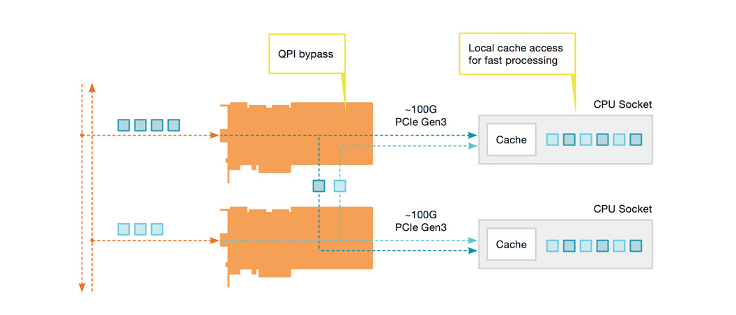
Multi-CPU buffer splitting enables Napatech Link-Capture™ Software to place captured frames in 1 to 128 host buffers. The customer can configure the size of the host buffers and how data is placed in the host buffers, based on results from the filter logic, port numbers and/or generated hash key values (flows). The advanced multi-CPU buffer splitting functionality and the option for distributing traffic to up to 128 CPU cores significantly improves the CPU cache performance, by always delivering the same flows and frame types to the same CPU cores.
QPI BYPASS FOR 2 × 100G PERFORMANCE SOLUTION
The Napatech 2 x 100G performance solution is based on two NT100E3-1-PTP FPGA SmartNICs, each providing a single 100G port with full throughput and zero packet loss under all conditions. Upstream and downstream are combined using QPI Bypass over Intelligent Hardware Interconnect. This allows specific flows to be combined and directed to the right CPU cores for processing in a balanced and controlled manner, without loading the server system with expensive communication between NUMA nodes.
4 X 10G CPU SOCKET LOAD BALANCER
Utilizes dual-CPU socket server for demanding data processing at 4 x 10G.
• Up to 30 percent performance improvement.
• No overhead from QPI transfer
• Direct cache access
• Full 4x10G throughput over SmartNIC interconnect
• Load distribution over up to 128 streams / CPU cores per SmartNIC
• Flexible configuration of load distribution
• Hashing with configurable field selection
• Tunneling and telecom protocol support
• Load distribution on inner IP addresses
HOST-BASED TRANSMIT
Multiple Tx streams, assigned to specific network ports, enable multi-threaded processing and full throughput bidirectional Rx/Tx for demanding traffic generation or in-line use cases. Alternatively, the SmartNIC can be configured in single Tx queue operation mode, where a port identification in the packet descriptor of each packet selects the egress port for the packet. This enables exact sequence and timing during replay of traffic captured across multiple ingress ports. The feature includes an API call for prepending protocol layers to Tx packets.
TRANSMIT ON TIME STAMP
Line rate transmit from application to network ports enables network simulation at 1G, 10G, 40G and 100G port speeds.
• Supports network test and simulation up to 100G line rate for any packet size
• Replay as captured based on time stamp
• Supported for 1G, 10G, 40G and 100G port speeds
• Transmits frames immediately or according to nanoseconds time stamp
• Configurable rate limiter for control of network load
• Replay of PCAP files
IN-LINE APPLICATION SUPPORT
Napatech Link-Capture™ Software supports in-line applications enabling customers to create powerful, yet flexible in-line solutions on standard servers. The more CPU-demanding the application is, and the higher the speeds of links, the higher the value of this solution.
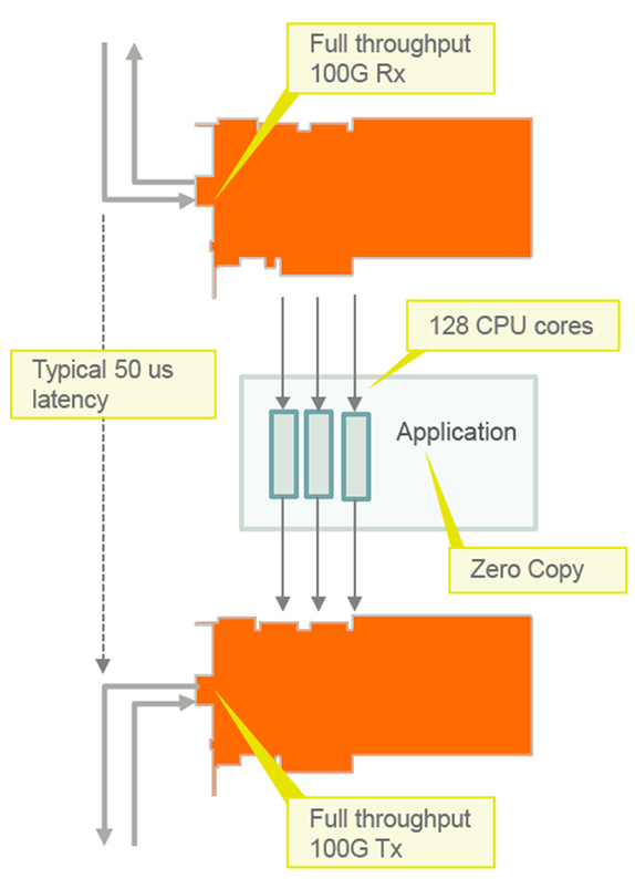
IN-LINE FEATURES
• Full throughput bidirectional Rx/Tx up to 100G link speed for any packet size (Depending on server performance)
• Supports multi-core processing with up to 128 Rx/Tx streams per SmartNIC
• Customizable hash based load distribution
• Zero copy transfer from Rx to Tx
• Single bit flip to select discard or forward packet •Typical 50 us roundtrip latency from Rx to Tx fiber
LOCAL RETRANSMIT
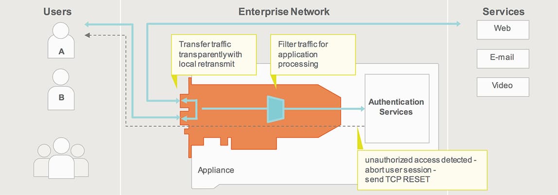
Forwarding of traffic from one port to multiple ports eliminates the need for expensive load distribution switch ports and smart tap.
• Up to 100G line rate for any packet size
• Forwarding of traffic from any port to multiple ports within the same SmartNIC
• Fully flexible solution where packets received on one port input can be forwarded to any port output and where multiple port inputs can be forwarded in parallel
• Controls which packets are forwarded and on which ports based on packet classification and filter functions
• Supported for 1G, 10G and 40G and 100Gport speeds
COMBINED HOST TRANSMIT AND LOCAL RETRANSMIT
Enables session control and low latency for in-line use cases.
• Transmit from application to any port – simultaneous local retransmit between ports
• Typically, less than 5 microseconds latency for local retransmit between ports
LOCAL RETRANSMIT WITH EMBEDDED TIME STAMP
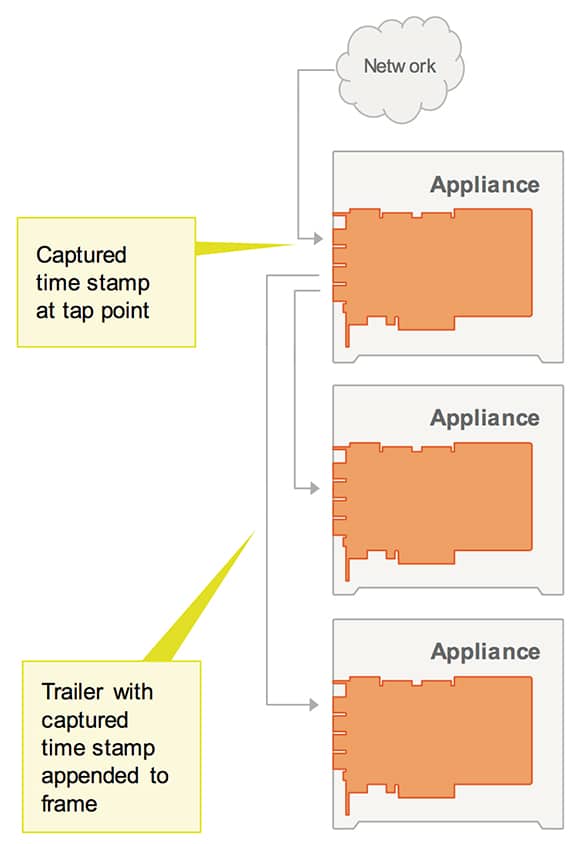
Avoid use of expensive load distribution switch ports, while delivering high precision time stamp to applications downlink.
• Preserves high precision time stamp captured at tap point, when using SmartNICs for load distribution or replication to other appliances
• Trailer with time stamp appended to retransmitted frame
• Configurable enable/disable per output port
In-line application support
Combined host transmit and local retransmit
ADVANCED STATISTICS
RMON1 PORT STATISTICS
Napatech Link-Capture™ Software provides RMON1 (RFC2819) counters on a per-port basis.
ADVANCED PORT STATISTICS
In addition to RMON1 port statistics, Napatech Link-Capture™ Software hardware generates an extensive amount of additional statistics counters, which are available independently of whether the traffic is forwarded to the host or not. This enables customer applications to retrieve a comprehensive network traffic analysis with extremely low CPU load.
Two types of statistics counters are available:
• Large sets: RMON1 (RFC2819) counters with extension of jumbo frame counters are available for both captured and discarded frames on a per-port basis.
• Normal sets: Frame and byte counters for good and bad frames are available per color (filter) and per host buffer.
Counter sets are always delivered as a consistent snapshot time-stamped by a 64-bit high-precision clock and can be synchronized with the Ethernet frames delivered for analysis.
MONITORING SENSORS
Sensors on the Napatech SmartNICs provide extensive monitoring of:
• PCB temperature level with alarm
• FPGA temperature level with alarm and automatic shutdown
• Temperature of critical components
• Individual optical port temperature or light level with alarm
• Voltage or current overrange with alarm
• Cooling fan speed with alarm
• Ethernet link status per port
• Status and loss of time synchronization
The system status can be read from the LEDs on the front of the SmartNIC. Possible alarms and error codes are stored on the SmartNIC for later troubleshooting.

